- Company
- Markets
-
Products
- Products
- Building cables
- Outdoor/Industrial Non Armored Cables
- Outdoor/Industrial Armored Cables
- Earth Conductors
- Solar farms
- Safety Cables
- Power Distribution Aerial cables
- Power Transmission & Distribution Conductors OHL
- Power Distribution cables
-
MV Underground Armored cables
- Overview
- CU/XLPE/CTS/LSF/AWA/LSF 6.35/11KV
- CU/XLPE/CTS/PVC/SWA/PVC 12.7/22KV RED STRIPE
- CU/XLPE/CTS/PVC/AWA/PVC 6.35/11KV
- CU/XLPE/CTS/PVC/SWA/PVC 6.35/11KV
- CU/XLPE/CTS/LSF/SWA/LSF 6.35/11 KV
- CU/XLPE/CTS/PVC/SWA/PVC 19/33KV RED STRIPE
- CU/XLPE/CTS/PVC/AWA/PVC 19/33KV
- CU/XLPE/CTS/PVC/AWA/PVC 12.7/22KV RED STRIPE
- CU/XLPE/CTS/PVC/SWA/PVC 6.35/11KV RED STRIPE
- CU/XLPE/CTS/PVC/AWA/PVC 6.35/11KV RED STRIPE
- CU/XLPE/CTS/PVC/AWA/PVC 19/33 KV RED STRIPE
-
MV Underground Unarmored cables
- Overview
- NA2XS(F)2Y RM 6/10 KV
- CU/XLPE/CWS/PE 6.35/11KV - BS 7870-4.10
- A2XS(F)2Y 12/20KV - IEC
- NA2XS(F)2Y RM 18/30 kV
- AL/XLPE/CWS/PVC 12/20KV - DEH
- NA2XS(F)2Y RM 12/20 kV
- CU/XLPE/CWS/PE 6.35/11KV - TRIPLEX - BS 7870-4.10
- 2XSY 12/20 KV - IEC
- AL/XLPE/CWS/PE 6.35/11KV - TRIPLEX - BS 7870-4.10
- AL/XLPE/PVC 12/20KV - triplex - Underground - DEH
- A2XSY 12/20KV - IEC
- CU/XLPE/CWS/PVC 12/20KV 3-CORE -IEC
- AL/XLPE/AWS/PE 6.35/11KV - TRIPLEX - IEC
- AL/XLPE/CWS/WB/PE 19/33KV - BS 7870-4.10
- AL/XLPE/CWS/PE 19/33KV - BS 7870-4.10
- AL/XLPE/AWS/WB/PE 19/33KV
- AL/XLPE/CWS/PE/SC 19/33KV - BS 7870-4.10
- A2XSH 12/20KV - DEH
- AXCLIGHT TT 12kV
- AXCLIGHT TT E 36kV
- NA2XS(FL)2Y V RM 12/20 kV
- AXCLIGHT TT 24kV
- CU/XLPE/AWS/PE 6.35/11KV - TRIPLEX - IEC
- AL/XLPE/AL-PE/PE 12/20KV 3.0 - IEC
- NA2XS(F)2Y RM 12/20 kV - triplex
- AL/XLPE/CWS/PE 6.35/11KV - BS 7870-4.20
- NA2XS(F)2Y V RM 12/20 kV
- AXLJ TT 36 kV
- CU/XLPE/AWS/LSF 6.35/11KV - IEC
- NA2XS2Y RM 6/10 KV - Triplex
- Newsroom
- Tools & Resources
- Newsletter
- Search
- Contact us
- Compare
- Sign in
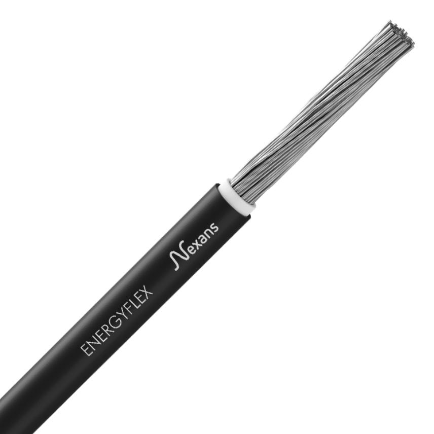
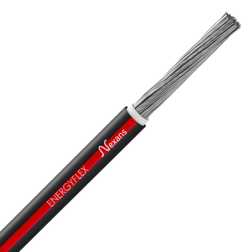
ENERGYFLEX ® 1 x 35 mm²


ENERGYFLEX ® 1 x 35 mm²
ENERGYFLEX
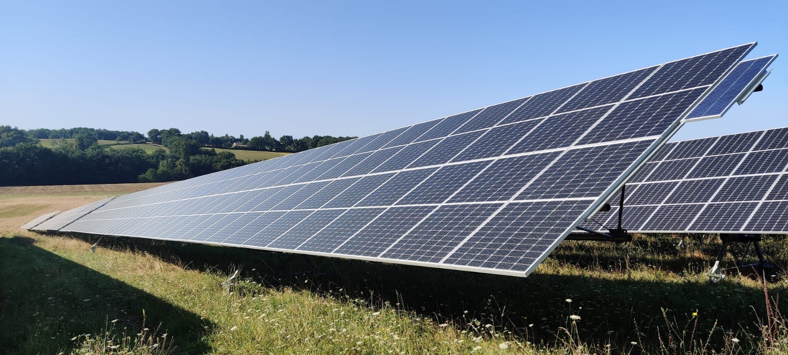
Energyflex® cables are designed to comply with the international standards of the solar plants.
They are dedicated to the photovoltaic system direct current (D.C.) side with a nominal D.C. voltage of 1.5 kV and a maximum D.C. voltage of 1.8 kV.
These cables are suitable for permanent outdoor long-term use, under variable and harsh climate conditions.
They are designed and tested to operate at a normal maximum conductor temperature of 90°C and for 20,000 hours up to 120°C. Therefore, the expected period use is 30 to 40 years under normal usage conditions (lifetime acc. to Arrhenius-Diagram).
Description
Description
Standards
-
ProductEN 50618; IEC 62930
Application
These state-of-art 1.5kV D.C. cross-linked Energyflex® cables offer exceptional performances, easy installation and long-term reliability for solar plant. They link photovoltaic panels for Utility-Scale solar plants or rooftops, and also connect them to the array box (if existing), or potentially to the inverter.
Design and recommended use
- Single core solar cable with low smoke, halogen free, cross-linked insulation and sheath.
- String Harness according to IEC 62548 Photovoltaic (PV) arrays - Design requirements.
Recommended Use
- Renewable Energies; Solar Plants.
- Intended for permanent use outdoor and indoor.
- Installation can be fixed or free movable / free hanging, and also in cable trays and conduits.
- These cables have a suitable behaviour in water : tests of Annexes D and E of H07RN8-F AD8 cables (100 days at 50 °C under 1 kV AC without breakdown) , and additionnal test of 1,5 year in hot water (85°C) under 1 kV DC without breakdown. They are suitable for submerged installations with a maximum cumulated immersion period of 6 months / year.
Complementary products
Energyflex® PV cables are part of the KEYLIOS® product range that includes:
- PV LV-DC String Harnesses
- LV-DC Aluminium core cable - unarmoured for above ground installation
- LV-DC Aluminium core cable - amoured for direct buried installaiton
- MC4 Connectors
- MV-AC Underground cables
Current rating temperature
Ambient temperature = 60°C
Maximum conductor temperature = 120°C
TECHNICAL INFORMATION (1/3)
|
Peroxide Crosslinked Material |
Halogen Free Material |
|
Cable insulation and jacket are both based on crosslinked polymers. Crosslinking is performed using peroxide technology. It means that the polymer macromolecular chains are physically bound by chemical links. The peroxide crosslinking is one of the most efficient ways to crosslink because it allows a crosslinking on a melt polymer, leading to a homogeneous network and a high density of links among the material thickness.
Advantages
Fig: The peroxide molecule decomposition leads to the formation of chemical bonds between polymer chains. After crosslinking, a three-dimensional network is obtained. The polymer chains are no more capable to slip among themselves and an infusible material is obtained with improved properties. |
Halogen based materials are widely used in cable industry with PVC and flame retardant additives. Halogens are a specific family of chemical elements: Fluorine (F), Chlorine (Cl), Bromine (Br), Iodine (I), Astatine (At). These elements are well-known to bring high performances regarding fire retardancy. However, they generate during the burning phase a heavy dark smoke with the formation of highly toxic and corrosive gases. Our Energyflex® cables are totally free of these elements.
Halogen content by Ion Chromatography Fig: A piece of material is burned in a tube and the emitted gases are carried and trapped for analysis. For a precise dosage of these different halogen elements, ion chromatography allows to separate these elements and to quantify accurately the amount of each species.
Corrosivity of smoke Fig: As seen before, a piece of material is burned and the gases are trapped in a liquid solution to measure the corrosivity of smoke. The pH and conductivity are measured and should be higher than respectively 4.3 and 10 µS/mm. |
TECHNICAL INFORMATION (2/3)
|
Long Term Thermal Endurance |
Sunlight Resistance |
|
The cable ageing under thermal oxidation leads to the degradation of the polymer material. To predict or at least to estimate what could be the lifetime of a material under thermal ageing, one uses the Arrhenius procedure depicted in the IEC 60216-1 to 4. The main principle is to age the material at high temperatures and then, using the Arrhenius law, to estimate/predict the lifetime at operating temperature (120 or 90°C).
Arrhenius plot Ageing was performed at 4 different temperatures: 135°C, 150°C, 165°C and 180°C. The line (linear plot) allows to predict the lifetime at 120 and 90°C. The red dots represent the main targets we are looking for, i.e. the 20000h@120°C, 25years@90°C and 40years@90°C. The more the extrapolated line is above the red dots, the more the lifetime is higher than the target. The obtained extrapolation is well above the targets and thus the estimated lifetime is bigger than 40years@90°C. ##image:101760:center## Fig: Arrhenius plot of the insulation material. The criterion to determine the time to failure is chosen as a loss of 50% of the initial elongation at break. At this stage, the cable has initiated it degradation but it is not fully degraded. |
One of the main causes of material ageing regarding photovoltaic application is the exposure to UV (Ultra-Violet) light, also called photo-degradation. The cable ageing under UV light is due to the combination of the temperature and UV irradiation (harmful UV irradiation is mainly between wavelengths 300 and 400 nm on the earth surface).
Accelerated ageing Our jacketing material presents no degradation after 1 month of weathering acc. to the EN 50289-4-17 method A. ##image:101761:center## Fig: The Xenon lamp generates a spectrum close to the sunlight one. The samples are placed facing the lamp and are submitted to a specific irradiance and temperature to accelerate the UV ageing.
Beyond the standard ##image:101762:center## Fig: Here in our Nexans process, we exceed the test conditions of the EN (4000hours against 720h and 100W/m² against 43W/m² specified) and we see no change of the mechanical features. |
TECHNICAL INFORMATION (3/3)
|
Dynamic Mechanical Performances |
Fire/Flame Retardancy |
|
No dynamic mechanical tests are found in the EN 50618 standard because the cables are intended to be used without any dynamic constraints. As Energyflex® could be used for Tracker systems, we have performed additional tests:
Dynamic behaviour Dynamic/cyclic mechanical constraints lead to the conductor degradation (copper/aluminium braid degradation). In our case, the cable present very good dynamic properties and still transmit current after 100 000 cycles in both torsion and bending. ##image:101765:center## Fig: Torsion cycles: 50N ± 135° 100°/s ##image:101766:center## Fig: Reverse bending: 100N ± 45° 160°/s |
Energyflex® cables are HFFR, i.e. Halogen Free Fire Retardant cables. The material is free of halogen and is capable to withstand a flame retardant test according to the EN 60332-1-2. It means that the cable presents a good resistance regarding the flame spread with a very good self-extinguishing behavior.
Resistance to flame test The cable passes the EN 60332-1-2 where 600mm of cable are tested vertically. The flame is applied with a 45° angle and a 1kW burner. ##image:101767:center## Fig: Picture of the flame test acc. to EN 60332-1. The flame is applied 1 to 8 minutes depending on the cable diameter. The test is compliant if after the flame application, the flame extinguishes with a burned length comprises between 50 and 540mm. |
PV
Characteristics
Characteristics
Construction characteristics
Construction characteristics
Dimensional characteristics
Dimensional characteristics
Electrical characteristics
Electrical characteristics
Mechanical characteristics
Mechanical characteristics
Usage characteristics
Usage characteristics
Resources
Resources
Documentation
Declaration of Performance
- Declaration of Performance n� : 1000199-
- Certification Date : 1/26/17
- AVCP (Assessment and Verification of Constancy of Performance) : System 3
- Notified body : NB 1812
- Declared performance : Eca
Our websites
Select your country to find our products and solutions
-
Africa
- Africa
- Ghana
- Ivory Coast
- Morocco
- North West Africa
- Americas
- Asia
- Europe
- Oceania
